




MOSFET vs IGBT: Hướng dẫn lựa chọn ứng dụng điện tử công suất
Mục lục
- [Hiểu về sự khác biệt cốt lõi] (#understanding điểm khác biệt cốt lõi)
- [Khi MOSFET thắng: Chuyển đổi tần số cao](#when-mosfet-thắng-chuyển đổi tần số cao)
- [Khi IGBT chiếm ưu thế: Ứng dụng điện áp cao, dòng điện cao] (#when-igbt-chiếm ưu thế-ứng dụng điện áp cao-dòng điện cao)
- [Sự đánh đổi giữa chi phí và hiệu suất] (#the đánh đổi giữa chi phí và hiệu suất)
- [SiC MOSFETs: Thay đổi trò chơi] (#sic-mosfets-thay đổi trò chơi)
- [Phương pháp lai: Hiểu biết bằng sáng chế của Tesla 2026] (#the-hybrid-approach-teslas-2026-patent-insight)
- [Tiêu chí lựa chọn cho hồ sơ của bạn] (tiêu chí #selection cho hồ sơ của bạn)
- Câu hỏi thường gặp
- Kết luận
Việc lựa chọn giữa MOSFET và IGBT không phải là thiết bị nào tốt hơn—mà là thiết bị nào phù hợp với yêu cầu power stage của bạn. Lựa chọn sai sẽ làm bạn mất hiệu quả, độ tin cậy hoặc ngân sách. Hướng dẫn này sẽ hướng dẫn bạn qua khung quyết định mà Hitop Tech Limited sử dụng khi xác định bán dẫn công suất cho các dự án của khách hàng.
Hiểu về sự khác biệt cốt lõi
MOSFET và IGBT đều hoạt động như các công tắc điều khiển điện tử, nhưng cấu trúc bên trong của chúng dẫn đến những hành vi hoàn toàn khác biệt.
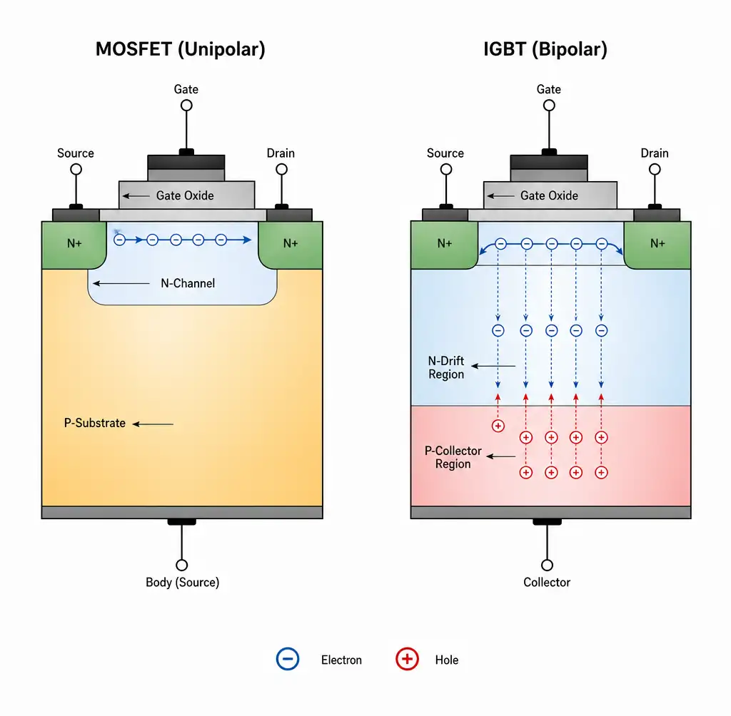 Mặt cắt cấu trúc nội bộ MOSFET và IGBT cho thấy dòng điện mang điện đơn cực và lưỡng cực
MOSFET là thiết bị đơn cực—dòng điện chỉ chạy qua electron. Điều này giúp chuyển mạch cực kỳ nhanh với dòng điện đuôi tối thiểu. IGBT kết hợp tầng đầu vào MOSFET với tầng đầu ra lưỡng cực, dẫn dòng điện qua cả electron và lỗ trống. Kết quả: giảm sụt điện áp trạng thái bật ở dòng điện cao, nhưng chuyển mạch chậm hơn với dòng điện đuôi đặc trưng khi tắt.
MOSFET có tổn hao chuyển mạch tỷ lệ thuận với tần số—gấp đôi tần số, tổn hao gần gấp đôi. IGBT mang một tổn hao tắt cố định mỗi chu kỳ do dòng điện đuôi đó, khiến chúng ngày càng kém hiệu quả khi tần số chuyển mạch vượt quá 20 kHz.
Khi MOSFET chiến thắng: Chuyển đổi tần số cao
MOSFET silicon chiếm ưu thế trong các ứng dụng khi tần số chuyển mạch vượt quá 20 kHz. Trong [bộ chuyển đổi DC-DC] (/sản phẩm/mô-đun cấp nguồn) cho nguồn viễn thông và máy chủ, các MOSFET chuyển mạch ở tần số 100-500 kHz mang lại hiệu suất vượt trội.
Ưu điểm chính của MOSFET:
- Dòng điện đuôi bằng 0: Tắt máy sạch và nhanh, thời gian chuyển đổi dưới 50 ns
- Khả năng song song: Hệ số nhiệt độ dương nghĩa là các thiết bị chia sẻ dòng điện tự nhiên
- Đơn giản hóa ổ cổng: Chỉ cần điện áp cổng 10-12V với điện tích cổng thấp
Trong bộ chuyển đổi DC-DC cách ly 10 kW chạy ở tần số 100 kHz, phương án thay thế IGBT sẽ cần bộ tản nhiệt lớn hơn 40% và vẫn cho hiệu suất thấp hơn 2%. Ở tần số đó, dòng điện đuôi IGBT chiếm 60% tổng tổn thất chuyển mạch.
Khi IGBT chiếm ưu thế: Ứng dụng điện áp cao, dòng điện cao
IGBT sẽ thay thế khi điện áp vượt quá 600V và dòng điện đạt hàng chục ampe, đặc biệt ở tần số chuyển mạch thấp hơn (1-20 kHz). Tầng đầu ra lưỡng cực giúp IGBT có độ sụt áp khi bật thấp hơn—thường là 1.5-2.5V bất kể dòng điện—so với đặc tính điện trở của MOSFET.
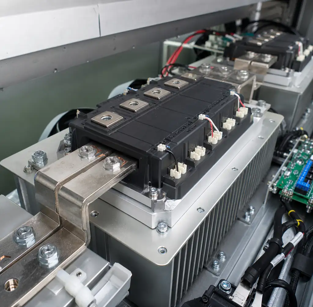 Mô-đun nguồn 1200V IGBT được lắp đặt trong bộ biến tần động cơ ba pha
Ưu điểm chính của IGBT:
- Tổn thất dẫn truyền thấp: Ở 50A và 1200V, mức giảm 2V của IGBT vượt trội so với tổn thất điện trở của MOSFET
- Khả năng điện áp cao: Có sẵn với mức công suất lên đến 6,5 kV
- Chịu chập mạch bền bỉ: Có thể xử lý các sự kiện chập mạch 10 μs
- Chi phí trên ampe: Ở dòng điện cao, IGBT có giá thấp hơn 30-40% so với MOSFET tương đương
Đối với [bộ truyền động động cơ công nghiệp] (/ứng dụng/tự động hóa công nghiệp) và bộ biến tần kéo, các bộ chuyển mạch IGBT ở tần số 4-10 kHz mang lại sự cân bằng phù hợp. Bộ biến tần ba pha 100 kW cho sạc xe điện thương mại sử dụng các mô-đun IGBT 1200V/400A — không có MOSFET silicon nào ở mức đó có hiệu suất nhiệt hoặc chi phí tương đương.
Sự đánh đổi giữa chi phí và hiệu suất
Chỉ riêng giá thiết bị thôi thì chưa đủ để nói lên toàn bộ câu chuyện. Bảng dưới đây phản ánh kinh tế ở cấp hệ thống mà chúng tôi xem xét trong các đánh giá thiết kế [lắp ráp PCB](/dịch vụ/lắp ráp pcb):
| Yếu tố chi phí | MOSFET silicon | Silicon IGBT | Tác động đến chi phí hệ thống |
|---|---|---|---|
| Giá đơn vị thiết bị (chuẩn hóa) | 1.0× | 0.7× | Tiết kiệm trực tiếp từ BoM ủng hộ IGBT |
| Độ phức tạp của trình điều khiển cổng | Đơn giản (10-12V) | Trung bình (15V, phân cực âm) | MOSFET tiết kiệm $2-5 cho mỗi kênh |
| Kích thước tản nhiệt (@10 kHz, 10 kW) | Trung bình | Nhỏ | Ưu điểm nhiệt của IGBT |
| Mạch giảm chấn/giảm chấn | Tối giản | Thường yêu cầu | Thêm $5-10 cho thiết kế IGBT |
| Khả năng chuyển đổi tần số | 100+ kHz | 1-20 kHz tiện lợi | MOSFET cho phép từ nhỏ hơn |
Điểm hòa vốn nằm quanh tần số chuyển mạch 20 kHz và điểm hoạt động 600V/30A. Dưới mức đó, IGBT thắng trên tổng chi phí. Hơn nữa, MOSFET mang lại hiệu suất tốt hơn và các linh kiện thụ động nhỏ hơn, bù đắp cho giá thiết bị cao hơn.
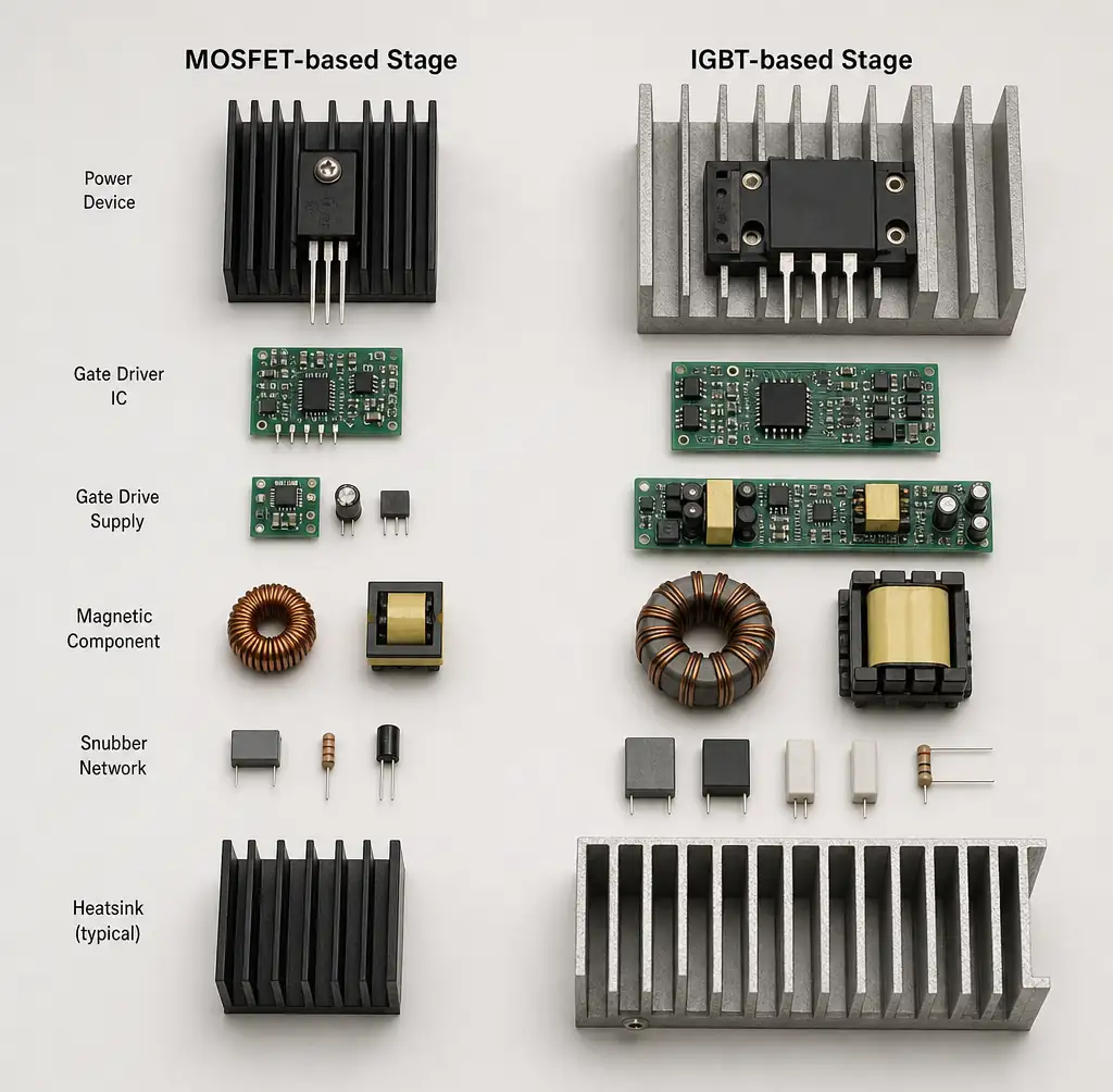 So sánh các thành phần song song cho thấy các yếu tố chi phí ở cấp hệ thống MOSFET và IGBT
SiC MOSFETs: Thay đổi trò chơi
MOSFET Silicon carbide (SiC) đã thay đổi căn bản bức tranh lựa chọn. Khoảng cách băng rộng giúp chúng có điện trở bật thấp hơn, khả năng chịu nhiệt cao hơn và chuyển mạch nhanh hơn so với silicon—cho phép MOSFET xâm nhập vào lãnh thổ IGBT.
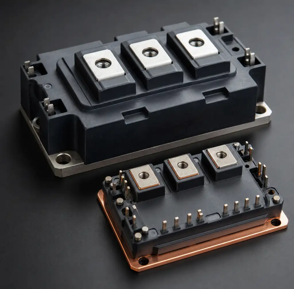 Mô-đun nguồn silicon carbide SiC MOSFET với thiết kế nhiệt nhỏ gọn cho bộ biến tần kéo xe điện
Ưu điểm đột phá của SiC MOSFET:
- Tăng hiệu suất 3-5% ở bộ biến tần kéo xe điện so với SI IGBT
- Hoạt động ở nhiệt độ cao hơn: Nhiệt độ nối lên đến 175°C so với 150°C đối với silicon, giảm yêu cầu tản nhiệt từ 30-50%
- Chuyển mạch nhanh hơn: Thời gian tăng/giảm 20-30 ns cho phép hoạt động 50-100 kHz trong bộ chuyển đổi quy mô kW
Tesla đã áp dụng bộ biến tần full-SiC trên Model 3 (2018), sử dụng mô-đun STMicroelectronics 24-die. Sự cải thiện hiệu suất đã chuyển thành phạm vi hoạt động tăng thêm 5-10 km. Đến năm 2026, hầu hết các xe điện cao cấp đều sử dụng MOSFET SiC — công nghệ này đã chứng minh hiệu quả trong lĩnh vực này.
Chi phí chênh lệch vẫn là thực tế nhưng đang giảm dần. Tính đến năm 2026, MOSFET SiC có giá cao hơn 2-3× so với SI IGBT ở mức tương đương, nhưng các khoản tiết kiệm ở cấp hệ thống (từ tính nhỏ hơn, làm mát giảm) thường hợp lý để chuyển đổi cho mức công suất trên 10 kW. Đối với khách hàng [điện tử công suất ô tô] (/ứng dụng/điện tử ô tô), SiC hiện là lựa chọn mặc định cho kiến trúc 800V.
Phương pháp tiếp cận lai: Khám phá bằng sáng chế năm 2026 của Tesla
Đơn đăng ký bằng sáng chế gần đây của Tesla (WO 2026/010828-A1, "Bộ biến tần kéo lai cho động cơ kéo điện") đề xuất đặt cả chip SI IGBT và SiC MOSFET vào cùng một bộ biến tần và chủ động chuyển đổi giữa chúng dựa trên điều kiện vận hành.
Khái niệm này hoạt động giống như hộp số tự động cho điện tử công suất:
"Cruising gear" (SiC MOSFET đang hoạt động): Khi lái xe ổn định trên đường cao tốc, bộ điều khiển ưu tiên các thiết bị SiC để đạt hiệu suất và phạm vi hoạt động tối đa.
"Bộ truyền động" (Si IGBT đang hoạt động): Khi bạn đạp ga hết cỡ hoặc kéo tải nặng, hệ thống sẽ chuyển sang các Si IGBT bền bỉ. Chúng khởi động trước—dẫn đầu tín hiệu SiC từ 100 nano giây đến 10 micro giây—để hấp thụ lực điện mạnh và bảo vệ các chip SiC dễ vỡ hơn.
Bằng sáng chế mô tả bố trí tỷ lệ 2:1: hai IGBT Si giá rẻ cho mỗi chip SiC đắt tiền, với thiết bị SiC được kẹp vật lý giữa các IGBT để cân bằng trường điện.
Kết quả là: rẻ hơn đáng kể để xây dựng so với hệ thống SiC đầy đủ trong khi vẫn cung cấp phạm vi hoạt động gần như tương đương. Cách tiếp cận lai này thừa nhận rằng các sự kiện công suất đỉnh rất hiếm nhưng lại quyết định mức độ thiết bị. Bằng cách để mỗi công nghệ xử lý những gì nó làm tốt nhất, bạn tối ưu hóa cho cả trường hợp phổ biến và trường hợp biên.
Tại Hitop Tech Limited, chúng tôi đang khám phá các cấu trúc lai cho [mô-đun sạc công suất cao] (/sản phẩm/bộ sạc xe điện) nơi cả chi phí lẫn độ bền đều quan trọng.
Tiêu chí lựa chọn cho hồ sơ của bạn
Sử dụng khung quyết định này khi chỉ định công tắc nguồn cho thiết kế tiếp theo của bạn:
| Yêu cầu đăng ký | Chọn MOSFET nếu... | Chọn IGBT nếu... | Xem xét SiC MOSFET nếu... |
|---|---|---|---|
| Tần số chuyển đổi | >20 kHz | <20 kHz | >20 kHz VÀ mật độ công suất cao |
| Mức điện áp | <600V | 600V-6500V | 600V-1700V VÀ hiệu suất cực kỳ quan trọng |
| Nhạy cảm về chi phí | Chi phí hệ thống quan trọng hơn | Chi phí thiết bị là yếu tố chính | Sẵn sàng trả 2-3× để đạt hiệu suất tăng 3-5% |
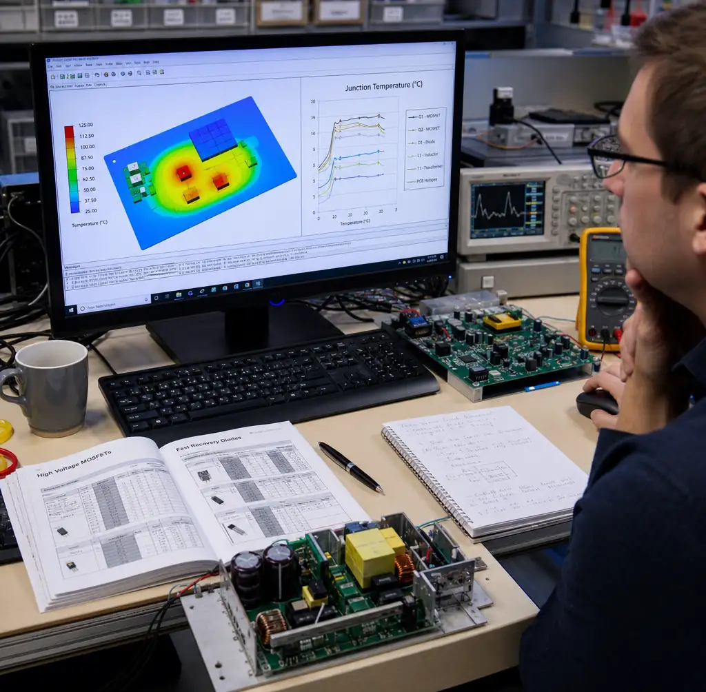 Kỹ sư điện tử công suất xem xét kết quả mô phỏng nhiệt cho việc lựa chọn MOSFET so với IGBT
Đối với [sản xuất PCB] (/dịch vụ/sản xuất pcb) và [nguồn cung linh kiện] (/dịch vụ/mua linh kiện), mô hình hóa toàn bộ chi phí hệ thống. Một MOSFET silicon có thể có giá 3 đô la so với 2 đô la của IGBT, nhưng nếu nó cho phép cuộn cảm nhỏ hơn 15 đô la và loại bỏ mạch snubber 8 đô la, thì MOSFET sẽ thắng.
Đừng quên người lái cổng. MOSFET chịu được các driver đơn giản ở phía cao. IGBT thường cần nguồn điện 15V cách ly với phân cực âm—tức là thêm $5-10 cho mỗi vị trí công tắc.
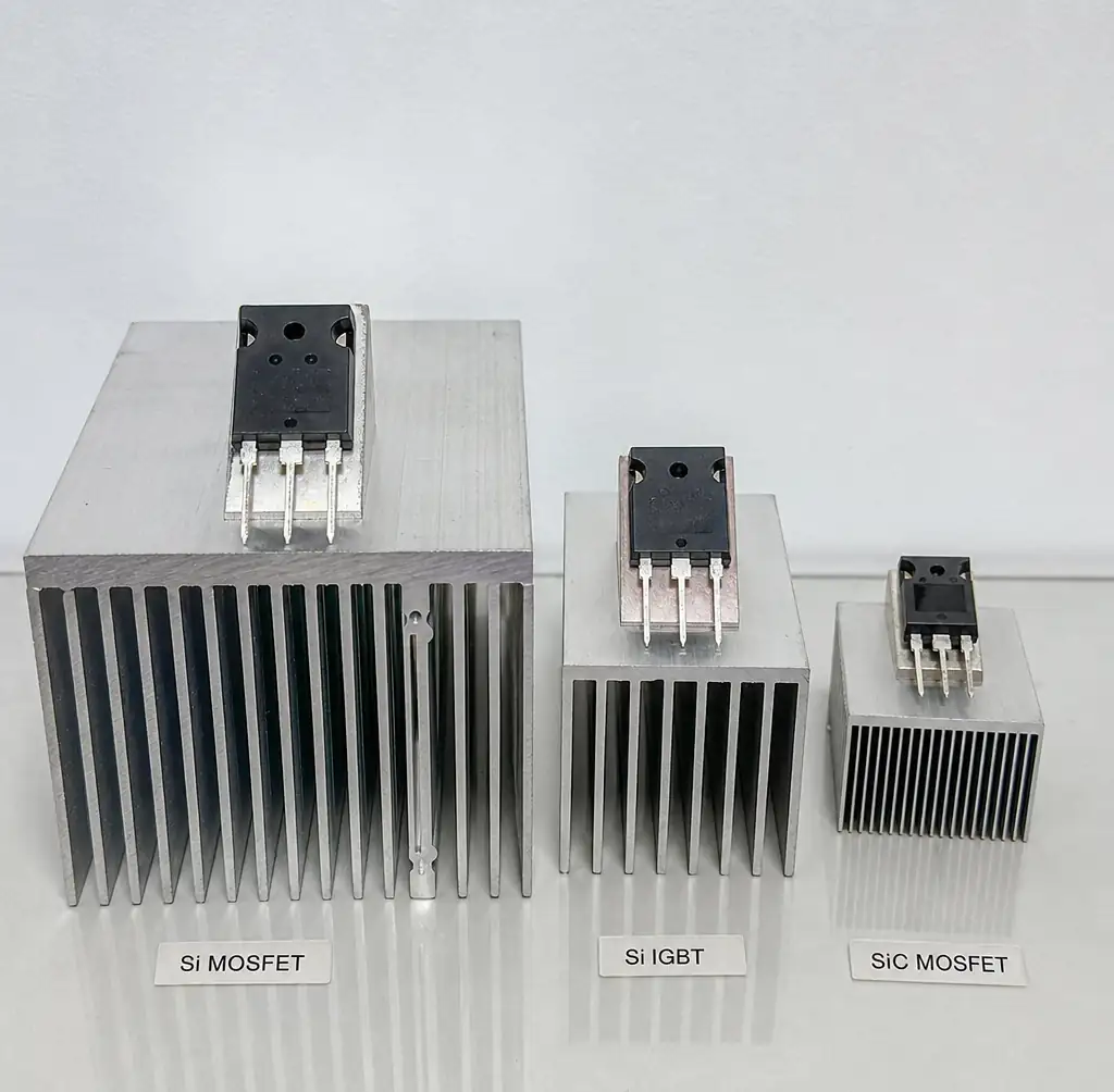 So sánh kích thước tản nhiệt cho thấy yêu cầu quản lý nhiệt cho Si MOSFET, Si IGBT và SiC MOSFET
Thực hiện phân tích nhiệt sớm. Một IGBT trông hoàn hảo trên giấy có thể cho thấy nhiệt độ mối nối vượt quá 150°C ở môi trường 40°C. Bộ tản nhiệt cần thiết làm tăng trọng lượng và chi phí đáng kể. Chuyển sang MOSFET SiC với chỉ số 175°C có thể loại bỏ hoàn toàn nút thắt nhiệt.
Câu hỏi thường gặp
Q: Tôi có thể đặt song song MOSFET và IGBT ở cùng một vị trí công tắc không?
Không. Đặc tính chuyển mạch và hệ số nhiệt độ rất khác biệt khiến việc này trở nên không thực tế. MOSFET có hệ số nhiệt dương (thiết bị nóng dẫn điện ít hơn), trong khi IGBT có hệ số nhiệt độ âm (thiết bị nóng dẫn truyền nhiều hơn, dẫn đến quá nhiệt). Bằng sáng chế lai của Tesla giữ chúng trên các tuyến đường song song riêng biệt với sự kiểm soát độc lập.
Q: Tại sao MOSFET SiC lại đắt hơn silicon rất nhiều?
Sản xuất wafer SiC vẫn phức tạp hơn silicon. Mật độ khuyết tật cao hơn, hiệu suất thấp hơn, và chi phí nền chỉ khoảng 5-10× so với wafer silicon. Tuy nhiên, wafer thế hệ thứ ba 8 inch đã giúp chi phí giảm 40% kể từ năm 2022. Dự báo ngành cho thấy SiC sẽ tiến gần 1,5× giá SI IGBT vào năm 2028-2030.
Q: SiC MOSFET có đáng tin cậy hơn SI IGBT không?
Dữ liệu hiện trường từ các lần triển khai EV 2018-2026 cho thấy các MOSFET SiC đáp ứng các mục tiêu độ tin cậy ô tô (tuổi thọ 15 năm, 150.000 dặm). Tuy nhiên, SI IGBT có 30+ năm lịch sử thực địa. Đối với các ứng dụng công nghiệp quan trọng, IGBT là lựa chọn bảo thủ nhất. Độ tin cậy của SiC đã được chứng minh, nhưng bộ dữ liệu nhỏ hơn.
Q: Còn transistor GaN thì sao—chúng nằm ở đâu?
Các FET Gallium nitride (GaN) xuất sắc ở tần số cao hơn (500 kHz-10 MHz) và điện áp thấp hơn (<650V). Chúng lý tưởng cho [nguồn điện mật độ cao] (/sản phẩm/mô-đun nguồn) và sạc không dây. Đối với không gian quyết định truyền thống giữa MOSFET và IGBT (>600V, >1 kW), GaN vẫn chưa đủ cạnh tranh.
Q: Tôi có thể cải tiến thiết kế IGBT bằng SiC MOSFET để tăng hiệu quả không?
Thường thì có, nhưng không phải là dịch vụ có thể đến bất ngờ. SiC chuyển đổi nhanh hơn, điều này có thể gây ra tiếng chuông và EMI. Điện áp ổ cổng có thể cần điều chỉnh. Giao diện nhiệt sẽ thay đổi vì SiC chạy nóng hơn nhưng cần ít tản nhiệt hơn. Ngân sách cho việc thiết kế lại bo mạch và kiểm tra lại EMI—hãy chuẩn bị cho 2-3 lần quay bo mạch để sẵn sàng cho sản xuất.
Kết luận
Việc lựa chọn MOSFET và IGBT phụ thuộc vào tần số hoạt động, điện áp, dòng điện và chi phí hệ thống—không chỉ riêng chi phí thiết bị. MOSFET silicon chiếm ưu thế trong các ứng dụng tần số cao dưới 600V và trên 20 kHz. Các IGBT silicon vẫn chưa bị đánh bại đối với các tầng điện áp cao, dòng điện cao trên 600V, nơi tần số chuyển mạch vẫn dưới 20 kHz. Các MOSFET SiC đang viết lại các quy tắc bằng cách cung cấp tốc độ MOSFET với khả năng điện áp IGBT, khiến chúng trở thành lựa chọn phù hợp cho các ứng dụng cao cấp, nơi chi phí cao hơn 2-3× biện minh cho việc tăng hiệu suất 3-5% và giảm 30-50% bộ tản nhiệt.
Bằng sáng chế biến tần hybrid năm 2026 của Tesla chỉ ra tương lai: đừng chọn một công nghệ duy nhất — hãy sử dụng cả hai khi mỗi công nghệ xuất sắc. Khi chi phí hội tụ và các nhà thiết kế ngày càng tự tin với các thiết bị khoảng cách băng rộng, hãy mong đợi nhiều kiến trúc lai và SiC chiếm ưu thế trong các hệ thống năng lượng ô tô, công nghiệp và tái tạo.
Tại Hitop Tech Limited, chúng tôi giúp khách hàng điều hướng những sự đánh đổi này trong [thiết kế PCB] (/dịch vụ/bố trí thiết kế pcb), lựa chọn linh kiện và [lắp ráp chìa khóa trao tay] (/services/turnkey-pcb-assembly). Quyết định đúng về bán dẫn công suất xảy ra sớm trong chu trình thiết kế. Tính toán các con số, mô hình hóa các tổn thất và lựa chọn dựa trên yêu cầu hệ thống của bạn—không chỉ dựa trên thông số kỹ thuật thiết bị.